Benefits - Ground plane independent - Simplicity - Built in triplexer effect 3 feed lines - Simultaneous transmission - No Bleed over between bands - Assumed gain. From the book the slim JIM was developed based on the basic J-Pole design see Fig1.
Dual Band Vhf Uhf Twinlead J Pole Antenna Pdf Notes 201903101154 1
Can not obtain good VSWR on 440 but the 2m gain is outstanding about 6dbd worth EXPERIMENT create you own unique designs the J is a very forgiving yet robust and.

. An efficient resonant antenna 14 wavelength or longer produces a large-amplitude EM wave for a given feed power and produces little heat. Convert a J Pole to a Slim Jim More Antenna Projects. The MARSians mass produced this antenna during the VHF frenzy in the mid-80s.
They are electric fence posts and come in 4 lengths 79cents The coax center conductor attaches to the long side of the J and the shield attaches to the short side 14 wave matching section. The J-pole I replaced at node K4ABT -7 alias 007 has increased the average signal at fifteen 15 miles by more than 5 db. If you need a super j use a piece of 34 pvc as the insulator and add the stub and another 38 or so inches of conduit.
This value is about 23-24 dB higher than the average gain of a single-radiator J-pole. It radiates and receives in an omni-directional pattern. Adjust tap point up down to find a match point.
Make the jout of 14 soft copper Solder it in place thru the hole and add the cable. 9 Simple J Pole Antenna Projects. The Tri-band J-pole by KB6EPO III.
Generally people dont think of radio-frequency radiation in terms of discrete. Vertically polarized antenna with two elements. ANTENNA THEORY ANALYSIS AND DESIGN THIRD.
Parts needed 10 ft of ½ copper pipe 3 T Fittings 3 M to F 90 degree elbow fittings 1 reducing fitting 3 feed lines of 50 ohm coax V. CB Antenna mounts SO-239 to 38-24 adapter 300Ω TV twinlead. This antenna does not need a ground to operate correctly.
A J-pole antenna K4KRW Collinear J-Pole Bob K9TMUs Slim Jim Variation on J-pole dual band easily built from a piece of 450 ohm ladder line. The J-pole antenna more properly known as the J antenna is a vertical omnidirectional transmitting antenna used in the shortwave frequency bandsIt was invented by Hans Beggerow in 1909 for use in Zeppelin airships. Looking for a design for a 270 antenna I came across this one1 Whilst a lot of people have come across a single band J-Pole The original antennae for GB3TR were J-poles constructed from 300 ohm ribbon cable and housed in 40mm plastic wastepipe I had never seen a dual band example.
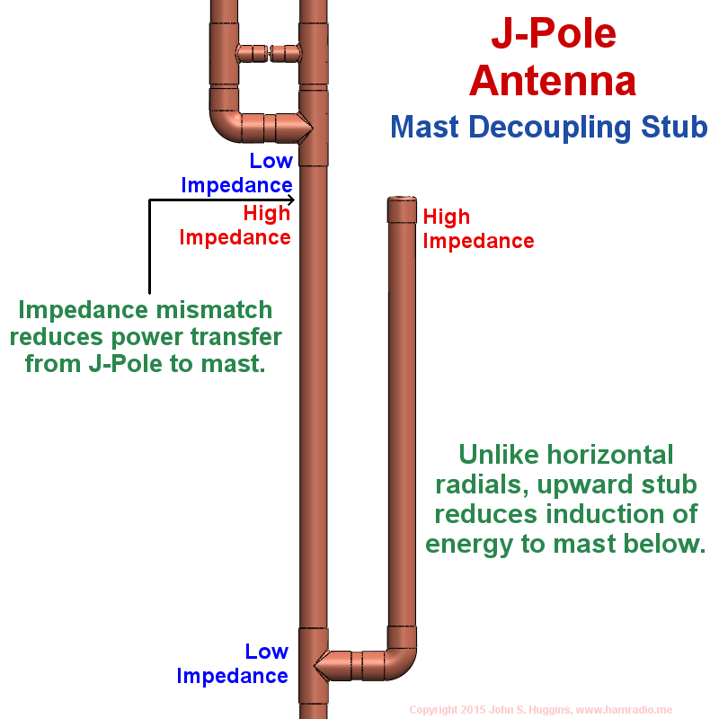
Simple J-Type 10m Vertical by W6IOJ Sept. This is important because if the mast extends above the antenna ground plane it will affect the performance of the antenna. Total cost for this antenna is under 10 excluding coax and it can be built in about an hour.
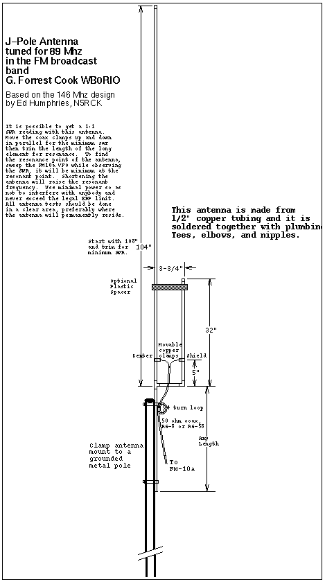
Indeed although many folks like to. A ¾ wavelength radiator and a ¼ wavelength matching stub. From the antenna so as not to affect the result Sweep the antenna from 144 MHz to 148MHz the SWR should be under 151 across the whole range For small adjustments tap the bracket up and down on the EMT with a screwdriver handle If the SWR is high open the range to 120 MHz to 160 MHz and see where the dip is.
Benefits - Ground plane independent - Simplicity - Built in triplexer effect 3 feed lines - Simultaneous transmission - No Bleed over between bands - Assumed gain. Intended physical length allowing a J-Pole antenna with a radiating section physically lengthened to 58-wave 49 inches to actually be radiating over a considerably longer length therefore radiating most of its power at useless higher angles and causing it to fall considerably behind the classic half-wave J-Pole design in performance. The raw materials to construct this antenna consist of a 5 feet of 300 ohm twinlead use the cheap stuff not the foam filled or shielded variety b 6 feet of 50 ohm co-ax and c a suitable connector to attach to your rig.
2 METER J-POLE ANTENNA This is perhaps the cheapest gain antenna for 2 meters that can be built. The J Pole antenna is a popular antenna design among amateur radio operators because it is effective and easy to build. Kinsner The design and implementation of a 2m J-pole antenna Technical Report DEL-92-1 November 1992 40 pp S 255fMHz 1-1316 F 272fMHz 1-78 RQ.
The J Pole antenna is a popular antenna design among amateur radio operators because it is effective and easy to build. It can be constructed from inexpensive materials at. For the bottom J section The coil forms are 38 fiberglass rods.
The J Pole antenna is a simplified version of the Slim Jim antenna using the same matching stub principle. The radiating element of this antenna must be clear of nearby metal objects by at least inchey If side mounted on an use 6 foot side mount Top of antenna may requÑe. Cost about 6 using new parts.
I found them at a local farm store. The construction plans presented in this newsletter are based on my new design and describe such an optimal antenna. This one looked particularly easy to construct with no.
Don Murray W9VE Building a Dual-Band Antenna Mentorfest 102304 16 An Even Better J-Pole - Electrically The gain is about 74 dBi. An inefficient antenna produces a small-amplitude EM wave for the same feed power and converts most of the power into heat. The ¼ wave stub cancels out ¼ wavelength of the ¾ wavelength radiator thus leaving ½ wavelength to radiate.
Invented by the Germans as Balloon Antennas and originally. Because of its J-pole design it requires no metal ground plane. The length of the antenna is three quarter wavelength.
440 Super J-Pole Antenna by KA0NAN April 1996. This picture shows that the base of the antenna is mounted flush to the top of the mast. However if mounted outside then an earth ground to the conduit is recommended.
It operates as an end-fed half-wave antenna. Using what is called Plumbers Delight construction I soldered all joints using a propane torch lead-freenon acid core solder and some soldering flux. The most recent antenna I replaced with a J-pole was a 2 meter see figure 1b aluminum base station commercially built amateur antenna purported to have more than 3 db gain over a dipole.
The J-Pole antenna became so popular in the VHF band because of its simplicity in design and construction. If installed per the dimensions above the antenna should have an SWR of less than 151 at both 146 and 444 Mhz. Copper Dual-Band Super J-Pole Antenna by KA0NAN April 1993.
This antenna design does not need a ground plane and is ideal for mounting inside PVC piping to protect it from the elements. Ulated supp ott at high wind ice elevationy 12 INCH COPPER. The J-Pole does not require any ground radials and has a antenna gain of 24dB over.
FIX ANTENNA TO MAST 2 INCH HOSE CLAMPY U BOLTS MAY CRIMP COPPER PIPE HOSE CLAMPS SECURE WELL IN MY NOTE. Allowing one additional flexibility in location. Top view side view of the 2004 motor-drive by Dominique Delerablee F1FRV source.
Commercial collinear base antennas multiple ⅝ wave elements means more gain lower takeoff angle. Its basically an end-fed omnidirectional half-wave antenna matched to the feedline by a quarter wave transmission line stub.
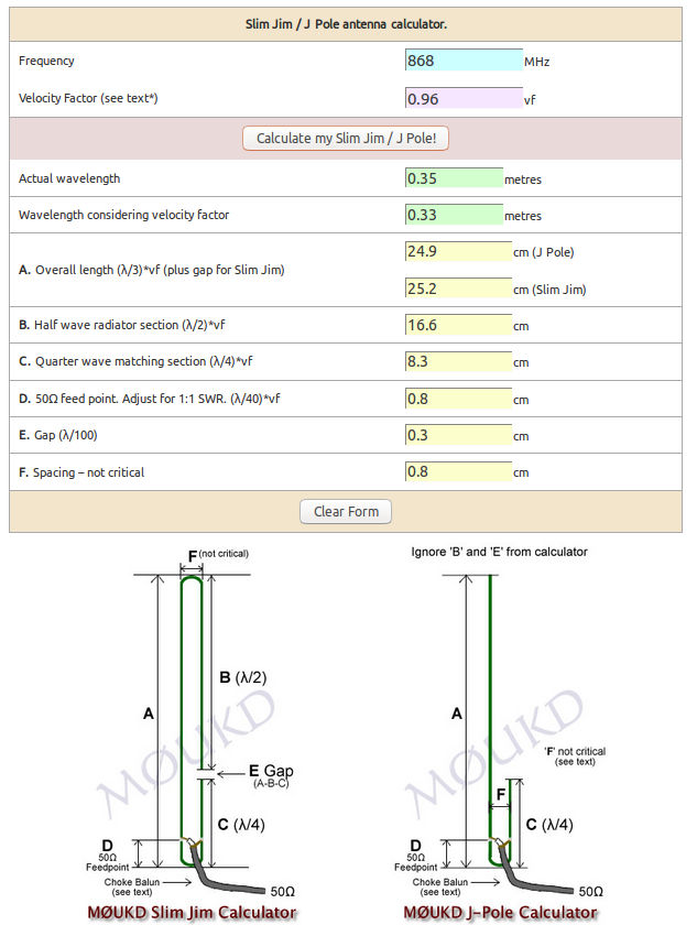
Antenna Experiment 868mhz J Pole Gateways The Things Network
.gif)
Antenna Projects
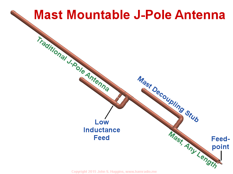
Mast Mountable J Pole Antenna
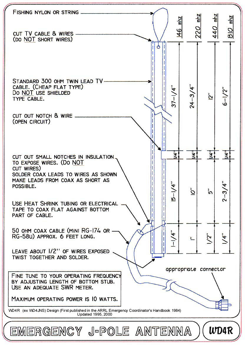
Emergency J Pole Antenna
Mast Mountable J Pole Antenna
Antenna Types J Pole Antenna Design

Pdf Modified Fractal Super J Pole Antenna
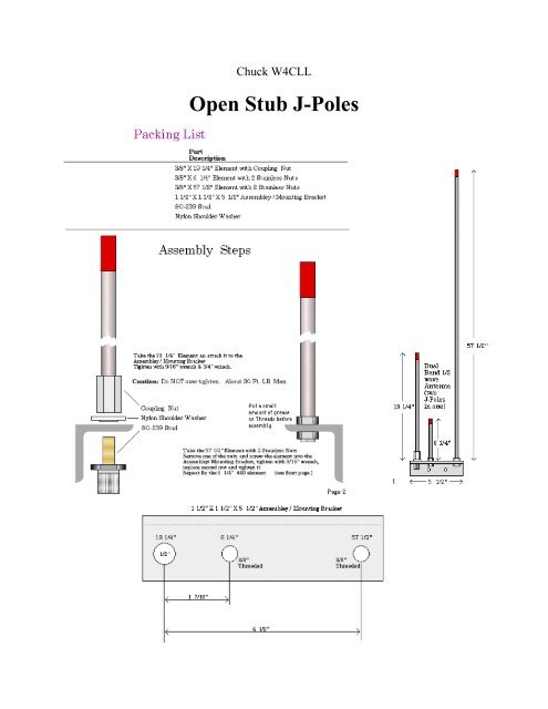
Open Stub J Poles Cascade Amateur Radio Society
0 comments
Post a Comment